| Version 13 (modified by indrek, 10 years ago) (diff) |
|---|

OWLTM Overview : Hardware
Introduction
This document describes the hardware components of the OWLTM system. It is written to give an overview of the system on the highest level. It shows the components, connections between the components, connections between the OWLTM and it's platform (ship/buoy/rig) and specifications.
Detailed datasheet? OWLTM Shipborne and
OWL MAPTM is attached.
Description of the measurement process is described in Physics of OWL^TM^.
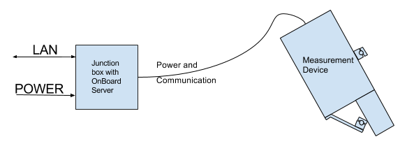
Block Diagram

The system has two components:
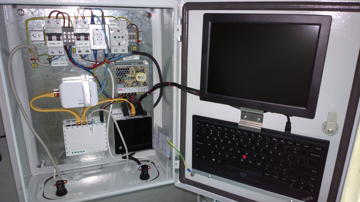
- Junction box that holds circuit breakers, power-line communication modem and server.
The junction box needs a LAN cable and a regular AC current from mains.
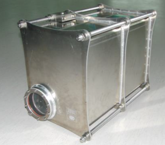
- Measurement device enclosed in a high durability, climate controlled aluminium box.
Also included in the box:
- 40 meters of heavy duty electrical cable for connecting Junction box and Measurement device. The Measurement device side of the cable has an space grade plug. Longer cable is available upon request, but the maximum length is 300 m. The maximum length is defined by the power-line communication.
- GPS antenna
- GPS antenna extension cord. The antenna must not be in the field of strong radio signal(for example ships radar) and the cord provides flexibility of choice on position.
- Custom made fastenings. The drawing of the railing is necessary for us to manufacture the components.
Specifications
| Operational | |
|---|---|
| Sensing | 5 to 30 m |
| Conditions of operation | Continuous, Day and Night |
| Sensitivity for oil products: | |
| Min concentration in water column | 1ppm |
| Min oil thickness on water surface | 1μm |
| Maximum detection depth | 3m |
| Pulse Repetition (Sampling) rate | Up to 100Hz |
| Sensing laser | Excimer type, XeCl, 308nm |
| Hyperspectral detector | Ultraviolet(UV) and visible spectral range |
| GPS | Integrated |
| Control and communication | |
| Operational control | Integrated micro-controller |
| Data storage | Local and central servers |
| Setup of device operation | Remote, via local server, embedded WEB |
| Communication line | Power-line communication |
| Alarm processing | Automatic |
| Data visualization on the map | Real-Time |
| General | |
| Power consumption | 150 W/(1500 W arctic) |
| Input voltage | 230VAC/50/60Hz |
| Dimensions (L x W x H) | 65 cm x 45 cm x 37 cm |
| Weight | 40 kg |
List of identifiable oil types
- Light oil
- Medium oil
- Crude oil
Safety The LASER in the measurement device is eye safe. See declaration of safety.
System installation

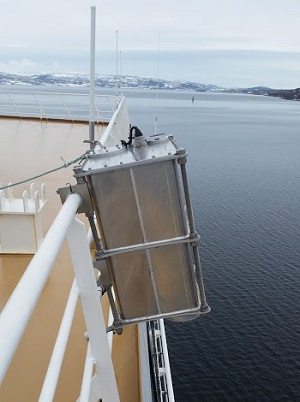
The Measurement device has robust attachment points along the longest edges. The customers needs to specify where the device is meant to be installed. A drawing of the railing is necessary for us to manufacture the appropriate fastenings.
The Junction Box should be installed indoors. The enclosure of the Junction Box is not weatherproof nor climate controlled. It is a metal box that will be mounted on a wall. It requires power and Local Area Network connections. The image below shows the typical setup. The Junction box size and shape may be altered to fit the customers needs. Even more so when optional screen and keyboard are removed.

Example of installed measurement device is shown below.

The system may be accessed from any computer on the same network. If the ship does not have any computer networks the computer in the Junction box will act as a system router and provide network control.
Attachments (7)
-
OV logo neutral medium.jpg
(67.7 KB) -
added by indrek 10 years ago.
Company logo
- Schematic of OWL.png (14.3 KB) - added by indrek 10 years ago.
- Photo of Measurement Device.png (378.6 KB) - added by indrek 10 years ago.
- Safety_sheet_B22.pdf (106.8 KB) - added by indrek 10 years ago.
- Photio of junction box.png (1.6 MB) - added by indrek 10 years ago.
- Installed measurement device.png (191.1 KB) - added by indrek 10 years ago.
- Ocean_Visuals_OWL_datasheet.pdf (2.0 MB) - added by indrek 10 years ago.
Download all attachments as: .zip